SKILLS NECESSARY
MATLAB
SolidWorks
Aerodynamics
Flight Control
Center of Gravity Calculations
Weight Distribution
FAA Regulations
Plane interior layout
Takeoff & Landing Verification
Cruising performance verification
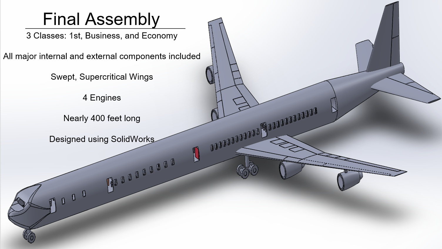
SUMMARY: Designed and modeled a 3-class jet aircraft (1st, business, and coach classes) that can fly internationally 7000 nautical miles and hold 250 passengers with their luggage. All basic equipment was represented minus the electrical system.
DESCRIPTION:
The main objective of this project was to design an aircraft that can realistically fly 7000 Nautical Miles and carry 250 passengers.
The first property that was determined was the size of the wings. When I write “wings”, I mean the main wings connected near the center of the plane, the Vertical Tail (VT) at the rear of the plane, and the Horizontal Tail (HT) also at the rear. All of the wings must be sized according to the loads placed on the wings as well as according to the function of the wings.
For example, the MAIN purpose of both the VT and HT is for control purposes instead of generating Lift. If the plane has more mass or has mission requirements that need the plane to have a higher velocity, then the HT and the VT need more surface area to account for those changes.
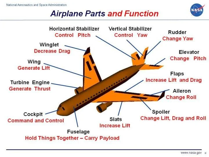
Courtesy of NASA; Source: https://www.grc.nasa.gov/www/k-12/airplane/Images/airplane.jpg
The same reasoning for sizing applies to the main wings as well - though there are several other factors to account for. For example, the types of engines installed on the wings make a significant difference to the size of the wings. Continuing the example, on most airplanes there are 4 engines with 2 engines installed on each wing. This is to ensure that if thrust is lost in one or more engines, there is sufficient leftover thrust to make the necessary maneuvers to keep the aircraft under control. With modern engines, however, only 2 engines total are needed because they are more efficient and provide more thrust than earlier versions. As a result, less wing is needed to support fewer engines.
Other considerations for the main wings include: Airfoil Shape (the side profile shape of the wing), Aspect Ratios (how “squished” the wing is), Taper Ratios (the thickness of the wing at the base vs. thickness of the wing at the tip), and the Sweep of the wing (how bent the wing is from the base of the plane body to the tip). By no account is this list complete but should give you an idea of the major considerations for sizing the wings.
In order to have the range and the number of passengers required, there is a balancing act between the placement of all of the equipment (inside and outside the main cabin) with the changing Center of Gravity (CG) located inside the plane. The CG determination is critical because it determines if and how your airplane flies; it is the characteristic most likely to tell you if the general design is feasible or not.
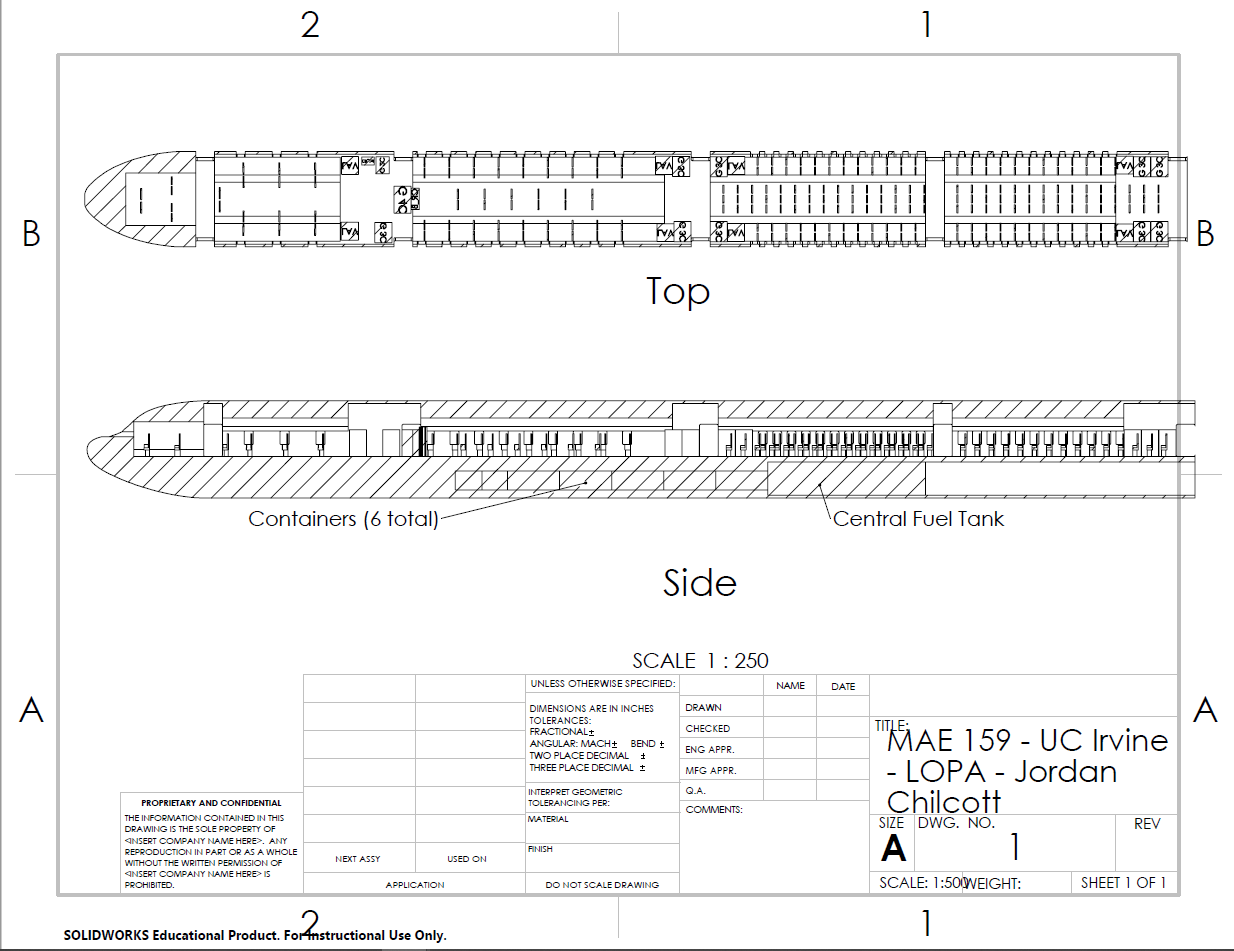
Layout Planned Area for the entire Airplane
If the CG is too far forward, the plane will nose dive. Conversely, if the CG is too far back, there will be major structural damage on Takeoff (TO) and Landing. Therefore, I needed to target a range of locations on the airplane where the CG must be placed in order so neither situation occurs. The acceptable bandwidth of the CG was found to be within around 4 feet. For a plane that’s just under 260 feet long, that’s a small range to work with.
To make sure the design was as safe as possible, it is crucial to design for the worst case scenario - when the CG is at either extremes of the acceptable range; this scenario occurs at both TO and Landing.
Additionally, we must consider the weight and location of the fuel due to the fact that jet fuel accounts for ~45% of the TOTAL weight at the time of TO; that means that by the time the plane arrives at its destination, the plane will have ~55% of its original weight! Because the fuel makes up such a large portion of the initial weight, the CG will most certainly change during the flight and it is important to control that change as much as possible.
Since CG is both an indicator of overall weights and locations, it is important to keep track of the overall layout at all times. The most important parts and locations to track were: 4 engines (2 engines if I decided to opt-in for more efficient engines), fuel & fuel tanks, all passenger seats in the 3 classes (including weight from people sitting in them), the luggage underneath, bathrooms, food carts, and other amenities wanted in the 3-class flight.
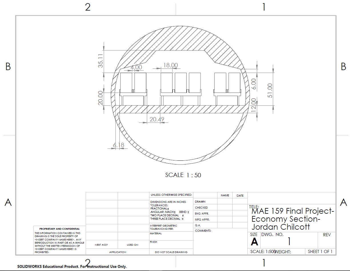
Cross Section of the Economy Section; units in inches
To figure out both the Wing Size as well as the CG, it was necessary to use an iterative process using MATLAB. Sizing the wing came first since most of the CG calculations relied heavily on Wing Surface Area and Wing Weight whereas Wing Sizing calculations can safely assume a CG with very little error. The basic structure of the Wing Sizing can be summarized as such:
Input basic mission requirements (Ex.: Mission Range)
Input the hardware you want to test (EX.: Jet Engine type)
Experiment with different wing characteristics (Ex.: airfoil shape)
Check solutions from 3) to see if the solutions are compatible with the original mission requirements
If a given solution is compatible with the initial requirements, then it gets saved to a database
If a given solution is not compatible, they repeat step 3)
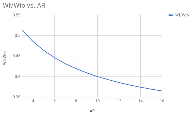
Example Consideration: Ratio of Fuel Weight over Takeoff Weight against the Aspect Ratio of the Wing
Once a range of solutions was established for the Wing Size, then I needed to figure out what CGs would allow the plane to fly. Before this step, however, I needed to address a serious problem: not all of the solutions to the Wing Sizing calculations are realistic. For example, an extremely thin wing thousands of feet long may theoretically solve the requirements but it is nowhere near practical. Once I figured out the problematic solutions and excluded them, I then input them into the next round of calculations: the CG calculations which can be summarized as follows:
Input realistic solutions of Wing Sizes into starting values of CG
Declare what airplane parts will be accounted for
Assign weights to all of the parts in the airplane
Experiment with the locations of the parts in the airplane to see if they are in the acceptable CG range with the reference point being the tip of the airplanes
If they pass the test, then add the solution to a separate database (different from Wing Sizing section)
If they don’t pass the test, keep trying with step 4)
Once these realistic solutions were found, I selected a particular configuration that met all criteria. From this configuration, I modeled the Airplane configuration in SolidWorks as the final step in this project.
To see further details about this project, please see the attached files in the “Results” section.