SKILLS NECESSARY
Thermodynamics
Fluid Mechanics
Aerodynamics
MatLab
Plotting
Technical Writing
SUMMARY: Designed basic turbo fan engine; Rendered data with carpet plots for selections

Turbo Fan engine of an Airplane
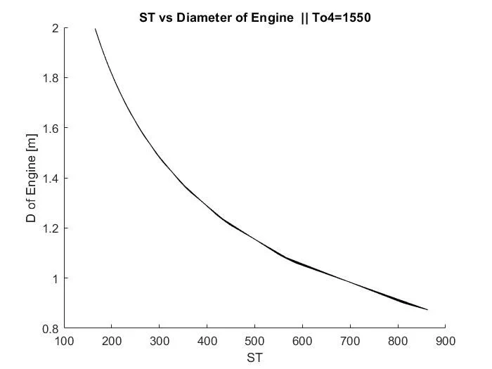
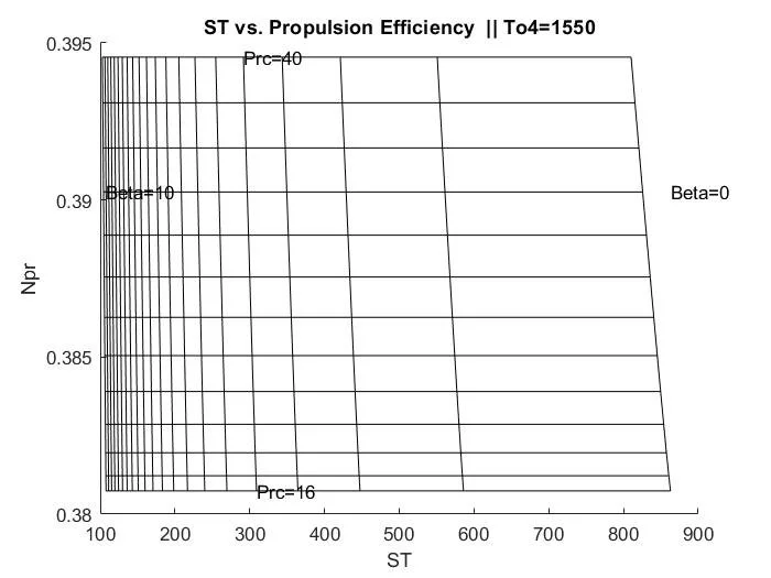
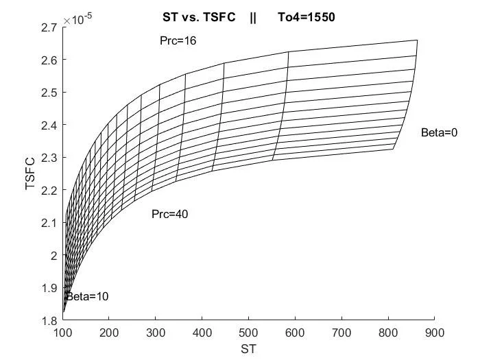
DESCRIPTION: The goal of the project was to design the engine of a turbofan for a required airplane size. More specifically, the mission was to create an engine of a passenger airplane capable of flying 800 miles (many round trips) using different engine configurations under cruise conditions, under max fuel savings conditions, and under max efficiency conditions. To determine the performance of the engine under these varied conditions, I calculated the different engine metrics (described later) and mapped said metrics of the different designs onto carpet plots I created in Matlab. The engine metrics I tracked included the Specific Thrust, Thrust Specific Fuel Consumption Rate, Required Inboard & Aft Diameters of the Turbofan Engines, Overall Efficiency, Thermal Efficiency, and Propulsion Efficiency.
The first task was to figure out basic thermodynamic ratios commonly used during engine design and to develop the methodologies and thought processes that go into setting up the analysis. This set up to analysis can be condensed into 12 basic steps:
Describe Inlet conditions at the compressor of the turbofan
Describe Outlet conditions
Describe the burner fuel-air ratio
Describe the Inlet Pressure
Describe the Fan Outlet Conditions
Solve for the Fan Nozzle Exit Velocity
Solve for the Turbine Outlet Conditions
Relate the Nozzle Inlet Conditions to the Fan
Solve for the Nozzle Exit Velocity
Calculate the Specific Thrust and Thrust Specific Fuel Consumption for the engine
Solve for the Propulsion, Thermal and Total Efficiencies
Solve for the Required Diameter


With the above information, there is enough information to create carpet plots and design the engine required for the mission.
At this point, it was suggested to students to solve for individual fan pressure ratios, then compression ratios, and finally map the quantities previously found onto graphs with those individual ratios. I disregarded that suggestion because I knew it would be more concise and clean (from a calculation perspective) to reduce the number of graphs by plotting more than two variables on a graph at a time. This was done because I knew by increasing the amount of variables on a graph, it’s easier to spot where optimal scenarios occur and you don’t have to shuffle between different - but similar - graphs. The main downside to how I created the graphs was that the coding became much more complicated. Trying to fit more than two real world independent variables onto a graph from a coding perspective can be quite a challenge.
Final Results: for max Total efficiency, an Inlet Temperature (To4) of 1400K was needed. To minimize Thrust Specific Fuel Consumption (TSFC) at 2.1 x 10^-5 (g/s)/kN, a bypass ratio (Beta) of 4 and compressor pressure ratio (pi_e) of 30.


For full details of requirements and results, please see the attached report.
RESULTS